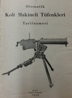
I recently found this in a private library, and I believe it’s the first Turkish-language manual I’ve come across. It’s dated 1936, and although the cover illustration shows a 1917 type water cooled gun, the manual actually covers the MG40 aircraft gun. This was a lightened, air-cooled Browning with dual feed, so it would be set up with the belt entering from either the left or right side as needed by whatever mounting it was to be put in. The basic design was taken from the model 1919 of WWII fame, but lightened to increase the rate of fire to 1100-1200 rpm. Colt sold nearly 70,000 of these guns between 1929 (when they were developed) and 1943. Most of those (49,681) went to the US government, with the next largest customer being the British RAF, which bought 11,960 of them. However, some 4,091 of these machine guns were sold commercially (source: The Browning Machine Gun Volume I![]() , by Dolf Goldsmith, pp 307-327).
, by Dolf Goldsmith, pp 307-327).
Most of the commercial guns went initially to aircraft manufacturers, who would mount them in military aircraft being produced for foreign government orders. This Turkish manual is an example of that – it accompanied guns mounted in aircraft built by the Curtiss-Wright Export Company that were being sold to Turkey. I don’t have a direct reference, but circumstantial evidence would suggest that these aircraft were Curtiss Hawk II fighters, each armed with a pair of Colt MG40 guns in 8mm Mauser. If you can read Turkish, you can find out all about how to operate and maintain the guns…and if you don’t read Turkish, the nice exploded diagrams will still be interesting:
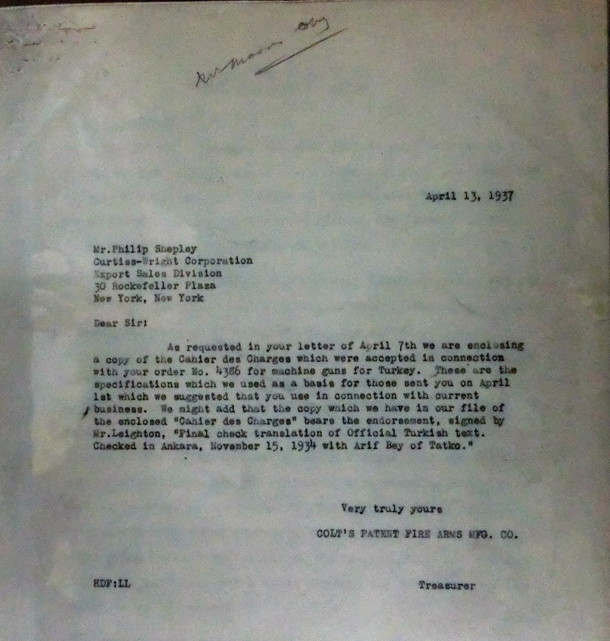
In addition to the manual, I found a copy of a letter from Colt to Curtiss referencing some changes to the gun contract:
I also found a blueprint for an 8mm metal disintegrating link for the MG40 (the drawing is for the stamped flat link, which would then have to be bent to final shape). Disintegrating link feed was much preferable to continuous belts for aerial use, as continuous belts would wind up jamming inside an aircraft wing or flapping out in the wind as they were being fired, whereas with a disintegrating belt each link could be ejected along with spend shell casings. Here’s the link drawing, for anyone who might want to reproduce them (although Israeli 1919 links work just fine in 8mm):


Neat! I’ll be sure to read these.
In case anyone was wondering about the title on the link drawing, the “blank” refers to the stamping itself, not the ammunition. A stamping that is a flat piece that has been cut to shape but not yet formed is called a “blank”.
Someone has written a note on it in cursive writing that is a bit hard to make out, but he seems to be questioning why there are no tolerances. Which I might add, is a very good question indeed. Note also that most of the dimensions are in thousandths of an inch, but some (but not all) of the radii are in 64ths or 32nds.
If no tolerances were given some old-school tool and die makeres would assume +/- 1 of the last digit of a measurement. Given that the drawing is in thousandths for the most part, that would imply +/-.001″, which is ridiculous for the non-critical dimensions for a disposible stamping. This is also pre-geometric dimensioning and tolerancing (GD&T), which really did not get started until WWII was in progress. Neither the thickness nor type of material is given, and there is no revision number on the drawing–maybe it was a preliminary working drawing sent to different departments for approval. The fractional radi might make sense if the tool and die maker was using a set of radius gauges to layout the die.
It looks like the design was to come out of 1″ wide strip, with the blanks nested to avoid waste. That day and age each link would have been picked up by hand and inserted into the next stamping operation–labor intensive and possibly dangerous. Leaving some metal on either side of the stirp and running it through a progressive die would have avoided handling individual blanks, but at the cost of more complex dies and larger presses and possibly more scrap. If the blanks were tumble deburred before final forming that may have required individual blanks.