This is a very unusual single-shot muzzleloading rifle. It is devoid of markings that might identify it, but appears (to my eye, anyway) to have been built from what was originally intended to be a turret rifle. It has a central puck-shaped block with a single chamber drilled in it. This puck sits inside a ring attached to the barrel. To load, the barrel is rotated 90 degrees, lining up a loading port in the ring with the chamber. To fire, a percussion cap is affixed to the back of the ring and the barrel is rotated back into line with the stock. What appears to be a front trigger is actually a manual cocking lever. The date of manufacture is unknown, as are any details about who it was made by or for, although the lack of proofs and the Kentucky-style stock suggest an American origin.
Accessories
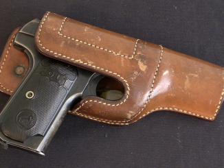
Audley Safety Holster and an OSS Colt 1903
F.H. Audley was a saddler who ran a business in New York City starting in the 1870s. As his business in horse tackle declined with the spread of automobiles, he found himself looking for other […]
Prototype
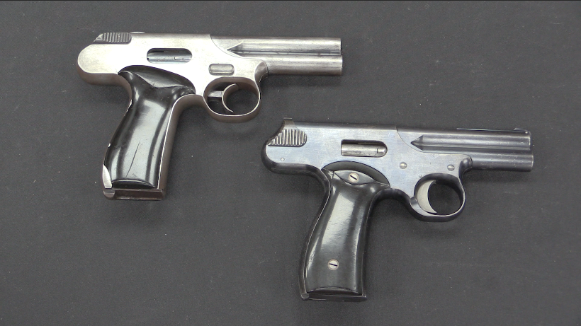
RIA: Odd Iver Johnson Prototype .32s (Video)
These unique and unmarked prototype .32 ACP pistols are apparently Iver Johnson prototypes – and I can’t find any information on them beyond that description from their consignor. One is a simpler example in the […]
Book review
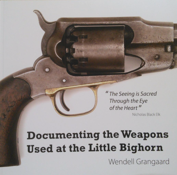
Book Review: Documenting the Weapons used at the Little Bighorn
I previously reviewed a book on archaeological study of the Little Bighorn battlefield, which did an excellent and very insightful job of tracing the battle through tangible artifacts, including forensic tracing of different individual weapons […]
I like it!
It’s actually a pretty elegant and sealed system for a breech loading percussion-lock long gun. The barrel gap is completely enclosed and the percussion-lock and nipple are completely protected in the firing position.
Perhaps the extra holes in the breech are lightening holes? Since not all the metal in the round breech block is needed?
“…are lightening holes?..”(C)
Very much like that. And even more, it looks like a rag oiler.
And the semi-round socket is for the ball lock.
I’ve seen this many times, on various homemade revolvers.
In this case, it didn’t work, so the latching pattern was changed to a leaf spring.
Apparently, it really was an experiment. And the blacksmith was dissatisfied with the accuracy of the shooting, so he tried to improve the fixation system. But nothing good came of it, because it couldn’t. A gun with such flimsy bedding cannot be accurate.
That is why so little was fired from it.
Possibly a “Pin-fire” for those other holes? It would need to have the “wheel” turned 90degrees up and the pin-fire bullets to have no rim and some type of saddle to bridge between the action and barrel. But I’m guessing!!
Most pinfire cartridges had no rim at all, because the “pin” held the cartridge in the proper place in the chamber.
I suspect the original idea might have been a smaller-caliber, pinfire revolver type action, with the “turret” turned through 90 degrees relative to the bore to act as a revolving longarm. It might have been intended to be an eight-shot judging from the spacing of the “holes”.
But before he got that far, the smith gave it up as a bad idea and used the half-finished “cylinder” for this. Waste not, want not, as they say.
cheers
eon
As Brad says above, the design details were likely to make a well sealed breach loading rifle.
The cylinder appears from the video to have a slightly tapered design, and this fits in a matching taper in the frame.
This could and likely did produce an excellent sealed fit that would be close to water and gas tight, providing a significantly better seal than a typical revolving cylinder, or the various turret designs, or the systems used on many other breach loading rifles of the time period.
The system may also seal up better than other rifles such as the Durrs Egg Ferguson rifles, and would likely have been far easier to machine, since two matching flat tapers are far simpler than a compound tapered thread.
Because of this design, the only area for gas to escape from is the percussion nipple.
The percussion nipple is also well placed, since it is nicely protected from having the percussion cap knocked off, and the hammer at rest looks like it might have even prevented the percussion cap from falling off, even if loose.
The swivel design could be bent for reloading with a height no more than that of a man laying with his torso raised on his elbows, so allowing reloading while still relatively out of the way of return fire.
The bent design might also allow for somewhat more easy reloading while on horseback.
The only main negative of the design is access for clearing a barrel obstruction, but that just seems to involve removing the two screws, and taking the rear cylinder out, and then maybe unscrewing the barrel from the ring if the obstruction is major, and unthreading the barrel might have been made easier with the hex section left on the barrel for the rear sight.
I’d honestly like to see this rifle shot to see how much gas leakage you get from the breech area.
Whoever designed this was rather ingenious, since most of the machining steps are relatively simple and allow for high precision.
The extra holes in the cylinder could be for lightening the cylinder, using a simply drilling method still used now from lightening AR receivers amongst other things. The holes would also have allowed for clearing of gunpowder residue similar to the grooves used on the cylinder shafts on revolvers.
“This could and likely did produce…”(С)
…system jamming after a few shots.
This sample is one of the most stupid ideas that I have ever (and I have) seen.
“ “This could and likely did produce…”(С)
…system jamming after a few shots. “
“This sample is one of the most stupid ideas that I have ever (and I have) seen.”
Stupid like the Colt Walker revolvers, which could get loaded with the supplied conical bullets placed backwards causing the revolvers to explode?
Stupid like the Martini-Henry rifles with their weak brass cartridge cases that tended to jam the rifle, making used cartridges difficult to remove if not completely disabling the rifle?
The system in this rifle is also way less complex to make, and potentially has a way better gas seal than the 1852 Sharps rifle
Gentlemen, I present you with the Kentucky Hockey Puck breechloading smoothbore musket!
Looks somewhat familiar to the experimental work of J.M.Browning’s father prior to the move to Utah.
How many did the Confederate Army order?
It would reload faster than a muzzle loader and, awkward though it looks, more easily inside a hide or blind. Or in a boat, say if you were potting geese or swans. The small caliber makes it (just barely) useful for the latter kind of hunting.
But it really looks like a failed try at making something unique. Remember: If at first you don’t succeed, give the hell up and don’t make yourself feel any more foolish than you have to.
But I’d sure like to see Ian try it out on the range. Wearing elaborate safety gear, of course.
Or, if you don’t succeed, try a different approach to the problem.
I’d say that it is a proof-of-concept patent model.
There were many such attempts at that time.
For example, https://patents.google.com/patent/US603
or https://patents.google.com/patent/US677
https://patentimages.storage.googleapis.com/95/45/87/a61140e40fa6eb/US20776-drawings-page-1.png
Not quite, but it looks like.
Patent drawings of that era often presented “idealized” images of what the inventor(s) had in mind. The actual product, if any, was often much simpler.
So yes, this could indeed be the patent model for that one.
BTW, the stock on the “real thing” looks like a “Maryland” pattern Pennsylvania rifle buttstock. the shape is distinctive. Not that many “Kentuckies” came out of Maryland.
However, this weapon having that pattern of stock, clearly made specifically for it, might be a clue as to where it was built.
cheers
eon
“…So yes, this could indeed be the patent model for that one…”(С)
I do not think so.
I’m pretty sure I’ve seen a patent VERY similar to this one.
How to find it among hundreds (or thousands) of others?..
This does look and sound like it might be it.
The Inventors on the patent are listed as Enoch Brooks and George Walker, of Philadelphia.
The Patent is dated July 6, 1858.
There’s an Enoch Brooks listed in the 1858 McElroy Philadelphia City Directory, as a Sea Captain, residing at 1405 Jefferson Avenue, I’m not sure if this is the same as the current Jefferson Street, or whether the current street numbering system would apply. If so, this would put the address near or at the location of the Alfred E. Burk House, but that was built between 1907-1909.
There are ten George Walker s listed in the same directory.
Amongst them there is a Segar Manufacturer(Cigar?), a Comb manufacturer, a Cordwainer?, a Salesman and a Lab? No of these professions are “gunsmith” machinist, but might have had machining experience due to manufacturing.
Philadelphia had lots and lots of manufacturing at the time, and for 100+ years before this, and many craftsman and shops that could have made a musket like this.
My guess is the stud and dimple arrangement was to take up the slack left from making the tolerances for two screws large enough to make assembly reasonably easy.
The holes + slots in the top of the puck being for oiling suggested earlier makes more sense to me than them being left over from a previous design.
“…makes more sense to me…”(C)
I see no other explanation.
This completely idiotic conical design would make sense if there was a screw underneath, like the ones used on old artillery piston breechs.
Soot from the shot will inevitably be stuffed into the annular gap and will inevitably lead to jamming of the system after several shots.
The author tried to overcome this by adding grease fittings and dirt collecting grooves, but apparently did not succeed.
This is a fairly common mistake among “nuggets” who have the most rough idea of technical design.
Blinded by their own genius, they do not consider it necessary to bother themselves with even the simplest critical analysis of the design.
And when it turns out that not a damn thing is working, they start sticking duct tape-over the plasters-over the scotch tape. Instead of taking a step back, spitting it out, and starting over.
I do tech support for scientific equipment. Add “with the standard part from the manual that we stock” and you’ve covered quite a few conversations I’ve had at work.
Mostly because the only person who knew where the manuals were stored retired. Their replacement is just delighted to find out we’ll email the manuals and point them to the right page.
I think you’re dead on about someone blinded by their own genius.
Given this must be 170 to 200 years old, I think completely idiotic is a little harsh for the design. Combining percussion caps with the first machine tools, I can see building a test rig.
But the nice (or maybe even fancy) stock and especially the sights point to someone figuring they had a no-fail idea.
I’m glad he was so cocky, because it is neat to see what he tried. The sealing system does work – it’s used in some high precision gas sampling valves. You just need materials and machining tolerances that weren’t possible until at least a hundred years later. And to keep any hard, sharp edged debris away from the sealing surfaces…
“ But the nice (or maybe even fancy) stock and especially the sights point to someone figuring they had a no-fail idea.”
It’s sort of common to have prototype or early examples of rifles made somewhat fancy, either to impress friends with your design, or to help sell the design to others.
The curly maple( or curly whatever wood) used for the stock was a fairly common wood at the time, and was routinely used for furniture, even furniture that wasn’t top of the line.( top of the line furniture used Mahogany, or Walnut burls etc) Curly maple or other similar domestic woods were routinely also used for rifle stocks even 100+ years earlier than this likely dates to.
It’s possible the stock was salvaged from another rifle.
It’s also possible the stock was just a commercially made rifle stock blank that was purchased to be finished with the new patented mechanism. I presume rifle stock blanks could just be purchased unfinished, since most other gun parts could be.
“ The sealing system does work – it’s used in some high precision gas sampling valves. You just need materials and machining tolerances that weren’t possible until at least a hundred years later. “
The mechanism using the central cylinder/breech block, and the outer ring “receiver” are basically two matching tapers.
Matching taper like this would be easy to manufacture with a basic metal lathe and experience. Even the primitive metal lathes were tooling was hand held would be capable of doing matching tapers with a basic jig made of an angled block of wood.
The tapers could also be fixed or matched if not completely smooth, by putting abrasives between the two tapers, and turning the two parts together to grind the tapers smooth and to perfectly match them.
If the central plug is made slightly thick, this can then be machined for thickness, which there seems to be marks of on the rifle parts.
The two parts can then be locked together using a clamp, be pressing the central plug into the outer ring, due to the taper, and the hole for the barrel could be drilled thru the two parts as one, ensuring a perfectly matching hole between the cylinder bore, and the rifle bore.
A smaller hole drilled first thru the outer ring and central cylinder could be used to locate the flash hole, and then enlarged with a larger boring tool used for the cylinder bore and the barrel bore.
The four holes drilled into the central plug, Breach block, whatever, appear to be symmetrically square.
A square steel or iron plate with four matching rods mounted in it, could have been used as a machining jig. With the central plug being clamped to the plate, the plate could then be used to hold the central plug in position for drilling, and to index the central plug easily at 90 degree angles for accurate drilling.
A lathe faceplate with four matching rods could also be used for mounting the central plug on for turning the plug round, since the plug, and possibly the outer ring could be simply held in place with the lathe tailstock pressing the center of the plug.
Using a custom lathe faceplate with mounting rods would have been way more elegant than using lathe dogs, which are still used nowadays.
“…And to keep any hard, sharp edged debris away from the sealing surfaces…”(С)
Is salt considered “hard, sharp edged debris”?
If so, you’re out of luck, as it is one of the main (60%) combustion products of black powder. 😉
This bit of information really only applies if the Enoch Brooks, George Walker patent is correct for this musket.
Enoch Brooks was a sea Captain, who Captained a ship during the 1850s called the Wyoming, that was a packet ship, sailing out of Philadelphia with a destination of Liverpool. The ship was owned by the wealthy Quaker Philadelphia Cope family(at that time as Cope Brothers), whose Liverpool agents were William and James Brown & Co., possibly the wealthiest merchants involved in the Atlantic trade.
This reminds me of a wrist-plate on a Corliss steam valve gear; the central wrist plate was housed inside an annular ring, like this gun, and had four attachment points for the four valve rods that connected to the four rotary valves. That might explain the four holes that don’t have a use in the gun itself. If you Google Fishkill Landing Machine Co and Fishkill Corliss engine, one of the drawings for the valve gear labeled “no. 50” shows the central wrist plate. I wonder if the gunmaker had some old steam engine parts, good hard steel, and repurposed this wrist plate? On this gun, there is no center hole bored vertically through the wrist plate for the axis pin/bolt shown in the drawing; maybe this was a surplus or spare that had not been fitted or completely finished, thus allowing the gun maker to bore horizontally through it to make the chamber and nipple/flash hole. On the gun on one side-plate, there is a fitting that is closed off with a screw; this might have been for an oiling tube to lubricate the original valve wrist plate.
Here are a few more.
https://patentimages.storage.googleapis.com/65/d1/33/a922d60a591cb0/US74152-drawings-page-1.png
https://patentimages.storage.googleapis.com/6b/4d/a7/f46b37b854f9c7/US35095-drawings-page-1.png
https://patentimages.storage.googleapis.com/b5/3a/96/b4a91d7bf86c4e/US33756-drawings-page-1.png
IMHO All the “courage” of these “attempts”, in an attempt to bypass one (or a couple) of really workable ideas in this direction.
Here is a thought, The holes with the grooves are there for self-cleaning. The grooves that go top to bottom scrape the residue and the larger grooves with the holes collect the residue and deposit it into the holes. This would self-clean the action every time you loaded it. When the holes are full, you would break the rifle down and clean the holes out.
Another thought: You fill the holes with grease, this would lubricate the action. I imagine this action would bind easily after firing it a few times and it warmed up.
It is just a couple of thoughts.
I think it is a really awesome rifle. Ideas like this led to much bigger and better ideas. To call this design “idiotic” is really sophomoric, and a narrow-minded response.